Jock.
2005-06-27 14:59:42 UTC
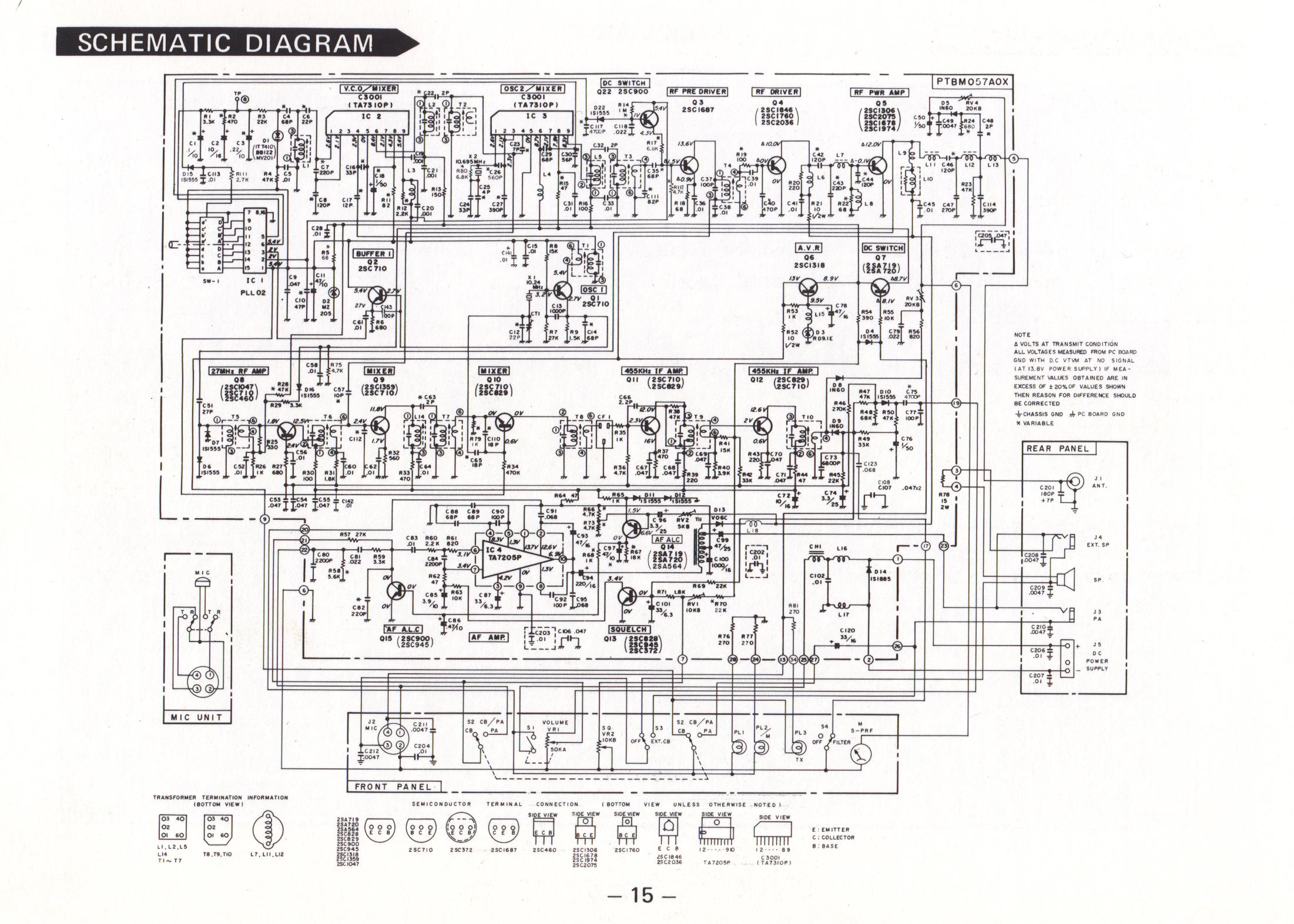
Does anyone know what the pinouts for the 6W audio
chip TA7205AP are?
1 to 10 left to right with manufacturer's markings
upmost?
Bitter experience taught me that things are never
quite that simple.
I have the Toshiba data sheet, but the bloody thing
does not give the pinouts!
73 de Jock.
chip TA7205AP are?
1 to 10 left to right with manufacturer's markings
upmost?
Bitter experience taught me that things are never
quite that simple.
I have the Toshiba data sheet, but the bloody thing
does not give the pinouts!
73 de Jock.
--
A wise man makes his own decisions,
A weak one obeys public opinion
- Credo Quia Absurdum
A wise man makes his own decisions,
A weak one obeys public opinion
- Credo Quia Absurdum